Here are tips and instructions for installing doorbells, buzzers or chimes. Take a few minutes to read the directions thoroughly. Following both these and manufacturers' instructions can save you time and effort while helping you achieve a satisfying finish. Inside this document you will find information about:


BASIC INFORMATION ABOUT DOORBELLS,
BUZZERS OR CHIMES

  • Wireless doorbells, buzzers and chimes consist of two units. The pushbutton unit is battery operated. The sound unit runs on household current provided by a regular outlet.

  • Most of today's doorbells and buzzers operate on 10 volts. Most modern door chimes operate on 16 volts.


  • Be sure the transformer you purchase with a doorbell, buzzer or chime is designed to provide the correct voltage for the mechanism you plan to install.

  • When you replace an older doorbell or buzzer with a new chime unit, you will probably have to replace the transformer too. The new transformer will provide the required voltage output.

  • If you are installing a battery-operated unit, you will not need to worry about transformers or power sources. These units are attractive enough to be installed on a wall in a room. Follow the instructions for button installation that matches the type of battery-powered unit you have–bell, buzzer, chime or combination.


FIG. 1 - A transformer reduces the normal 120-volt power to 10 or 16 volts.


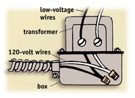
FIG. 2 - Most transformers are mounted directly on the junction box.

INFORMATION ABOUT THE TRANSFORMER

  • On the newer doorbell, buzzer and chime units, the transformer is built into the unit. This eliminates the need for a separate transformer. When working with older systems you will need a separate transformer.

  • The 16-volt transformer needed for chimes is slightly larger than the 10-volt transformer used for bells or buzzers.

  • Both transformers are relatively small and fit into small areas such as outlet boxes.

  • A transformer (Fig. 1) reduces normal 120-volt power to 10 or 16 volts, thus adapting regular current to low-voltage equipment such as chimes, buzzers and bells.

  • A transformer usually has two permanent wires–one white and one black–designed to provide power to the unit from the power source.

  • Two attachment screws are mounted on the opposite side of the transformer for attaching low-voltage wires that in turn are connected to the bell, buzzer or chime (Fig. 1).

  • Most transformers are designed so they can be mounted directly to an outlet or junction box (Fig. 2). The primary power source wires can then be run directly into the box.

  • If the transformer is not mounted directly to the outlet or junction box, the connecting 120-volt wires should always run through safe, insulated connectors and be spliced inside the box.

  • Use No. 18 bell wire to connect to the two terminal screws on the low-voltage side of the transformer. Even though the voltage on these transformers is very low, you must still practice the rules of safety. Turn off the power before you start to work.

  • Use insulated staples to hold the bell wire in place. It is normally run along baseboards or in other exposed areas in a room.


FIG. 3 - This simple wiring system is used for single-button doorbells.


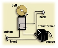
INSTALLING A SINGLE-BUTTON DOORBELL

  • The simplest doorbell or buzzer installation is the wiring illustrated in Fig. 3. In this instance, a button is mounted on one door only to operate the buzzer or bell.

  • One wire runs unbroken from the terminal screw on the button of the bell or buzzer to the terminal screw on the transformer. The second wire runs from the button to one of the terminal screws on the bell, then from the second terminal screw back to the other screw on the transformer (Fig. 3).

  • The button can be mounted on any door–as far away from the bell as you'd like–and the bell and transformer can be mounted in any concealed location.


FIG. 4 - The illustration shows the wiring for bells at the front and back doors.


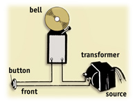
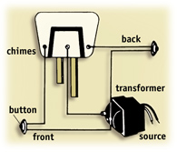
WIRING FOR BUTTONS ON FRONT
& BACK DOORS

  • When you would like to have doorbell buttons on both the front and back doors, one wire goes directly from the terminal screws on both the front and backdoor buttons to one of the terminal screws on the transformer (Fig. 4).

  • The second wire goes directly from the other terminal screw on both buttons to the terminal screws on the bell (Fig. 4).

  • Finally, a third wire connects to the left terminal screw on the bell and to the other terminal screw on the transformer (Fig. 4).

  • One disadvantage to this system is that the person hearing the bell from inside the house never knows whether to answer the front or back door since both buttons activate the same bell sound.


FIG. 5 - Use this system for wiring for a buzzer to the back door and a bell to the front door.


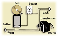
WIRING FOR A BACKDOOR BUZZER & A FRONT DOORBELL

  • One way to solve this problem is by installing a bell and a buzzer. Try using a buzzer at the back door and a bell at the front door (Fig. 5).

  • Use the wiring system shown in Fig. 5 for wiring a buzzer and a bell at two different locations. The wiring is basically the same as in Fig. 4, except the buzzer is wired in between the terminal screw on the backdoor button and the terminal screw on the bell.

  • The buzzer, bell and transformer can be concealed in any location. This works well if you already have either a bell or buzzer installed. If you do not, consider a combination bell and buzzer unit to simplify installation and reduce cost.


FIG. 6 - The wiring arrangement for a combination bell and buzzer is shown here.


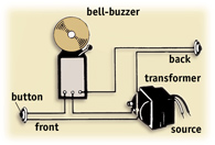
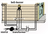
WIRING ARRANGEMENT FOR COMBINATION BELL & BUZZER

  • A combination bell and buzzer gives you a buzzer for the back door and a bell for the front door in one unit (Fig. 6). You'll notice that this unit has three terminal screws rather than two.

  • Follow the wiring arrangement shown in Fig. 6 for installing the combination bell and buzzer unit so the bell rings when the front door button is pushed and the buzzer is activated at the back door.

  • The bell and buzzer should be placed so that the sound can be heard throughout the house. The sounds from bells and buzzers hidden deep in attics or closets may be muffled–and even completely shut out.


FIG. 7 - The best location for the transformer may be in your basement.


LOCATING THE TRANSFORMER IN
THE BASEMENT

  • The best location for the transformer in many homes is the basement. Fig. 7 illustrates how to connect the transformer to an outlet box in the basement, while the wiring is run to the front and back doors and the bell and buzzer unit. Run low-voltage bell wire along the baseboard and around door frames, and use insulated staples to hold the wire in place. Such bell wire is neither expensive nor unsightly.

  • Always select a transformer with overload protection on the secondary or low-voltage wiring. Built-in protection of this type will cut off the current when trouble occurs in the transformer.


FIG. 8 - The wiring for one- and two-note chimes is similar to the wiring used for doorbells and buzzers.


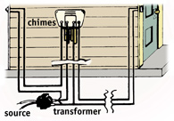
WIRING FOR DOOR CHIMES

  • Many homeowners enjoy the sound of chimes rather than doorbells or buzzers. Chimes are attractive, and the sound is very pleasant.

  • Most chimes already provide separate tones for your front and back doors. This makes it easy to determine from which door the chime is activated.

  • Chimes of various types are available for you to use. A four-note chime unit may sound single notes for the back door and as many as eight notes for the front door. The wiring diagram in Fig. 8 shows how to wire a dual-chime unit for one note to sound from the back door and two notes to chime from the front door. You'll notice the similarity between wiring a chime and a doorbell or buzzer.

  • Chimes are usually much more attractive than bells or buzzers. For this reason, you may want to mount them right on the wall in a room.

  • Again, remember that the chime should be mounted in a location that allows you to hear the chimes throughout your home.


FIG. 9 - Simple wiring plan for a four-note chime.


WIRING A FOUR-NOTE CHIME

  • Always use a heavy transformer (16 volts to 20 volts) that matches the voltage requirement for a larger chime.

  • Read the manufacturer's instructions and follow them carefully. Many larger transformers require specific wiring arrangements.

  • Fig. 9 shows a simple wiring plan for a four-note chime.

  • In the illustration, the transformer is located in an outlet box in the basement, and the wire feeds to the four chimes in the central unit located elsewhere within the house.


LOCATING TROUBLE IN
BELLS & CHIMES

  • Use a low-voltage circuit tester for testing the wiring arrangements for doorbells, buzzers or chimes. This type of tester is readily available at most hardware stores and home centers for a very reasonable cost.

  • When problems arise, the doorbell button is usually the culprit. Always check the button first if a doorbell or chime fails to function. Metal fatigue in the spring or corrosion from the weather may cause the contact point to fail to function.

  • After checking the bell button, inspect all visible sections of the wiring for breakage or mechanical damage.

  • Use a low-voltage tester on each section of the wiring. You will probably locate a break in the wiring rather than a short.

  • The bell will continuously ring–even when the button is not pushed–if you have a short somewhere in the wire.


  • If the transformer has an overload protection device, a shortage may cause it to cut off the secondary current. So, the transformer should also be checked when problems occur.

  • To check the transformer, disconnect one wire from the transformer's secondary screw. Touch the low-voltage terminal and the disconnected wire with the low-voltage tester.


  • The bulb will light if there is a short in the wire. Be sure that the bulb you use in the low-voltage tester matches the voltage in the transformer. If you are using a lower-voltage bulb, it will burn out during testing. If you are using a bulb with a high-voltage rating, the light will simply be dim.

  • Use a low-voltage tester to test the doorbell button. Connect the button from one transformer terminal through the bulb tester and back to the other terminal. If the button is working, the bulb will light when the button is pushed.


  • If the trouble seems to be in the bell, buzzer or chime, the problem is usually in the connections at the contact point. Remove each connection wire, file it with sandpaper and replace each wire.

  • More expensive chimes have solenoids that may be very difficult to replace. In some cases, these solenoids burn out and the chimes will fail to function. You may need to return the chime to the manufacturer for repair.


  • When first installing a wireless unit, if the unit fails to operate, try plugging in the sound unit closer to the location of the pushbutton. You may just be out of the range of the small transmitter in the pushbutton.

  • With the wireless units a weak battery in the pushbutton may cause the unit not to work. Check the battery with a low-voltage tester set to DC volts. If the battery is weak, replace it.


TOOL AND MATERIAL CHECKLIST
Doorbell Chime
Insulated Staples Side-Cutter Pliers
Transformer Keyhole Saw
Hammer Low-Voltage Tester
Buzzer Bell Wire
Pliers Electricians' Tape
Doorbell Button(s) Screwdriver
Stapler Screws

Check your state and local codes before starting any project. Follow all safety precautions. Information in this document has been furnished by the National Retail Hardware Association (NRHA) and associated contributors. Every effort has been made to ensure accuracy and safety. Neither NRHA, any contributor nor the retailer can be held responsible for damages or injuries resulting from the use of the information in this document.